
Electronic Eye Controlled Security System is an electronic instrument that notices your home if anyone is visiting. The primary principle of this system is to ring the doorbell automatically when a person visits your home. LDR light determines if the person is currently present or not. This system provides security when a person is trying to enter your home.
Electronic Eye Controlled Security System Circuit Principle
The prime principle of the electronic eye controlled security system circuit is to ring the doorbell when a person enters the home. To detect the person entering the home, an LDR is used as a sensor. The light on the LDR determines if the person is present or not. When a person enters the home, the LDR changes its colour and a buzzer begins to ring. Additionally, the LED light also starts glowing.
Circuit Components
- 7805 Regulator
- Transistors – BC 547 x 2
- 1N4007 PN Diode
- Resistors – 220Ω x 2, 1KΩ x 2, 100KΩ
- Capacitors – 1µF, 10µF
- LED
- Buzzer
- Light Dependent Resistor (LDR)
- 9V battery
- Connecting wires
- Breadboard
Circuit Design
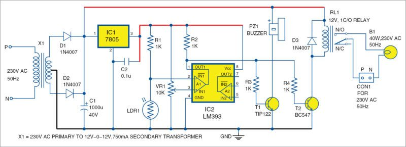
The circuit is divided into two sections. One is the power supply and another is the logic circuit. A 9V supply from a battery is transformed to 5V in the power supply circuit. When a shadow falls on the LDR, the logic circuit raises a buzzer and LED light starts glowing.
Design of Power Supply Circuit
The power supply circuit containsa battery, regulator, diode,and capacitors. A 9V battery needs to be connected to the diode. The diode is a simple P-N junction of the 1N4007 series. Here, 1N4007 is connected to the forward bias condition. The primary purpose of the diode is to protect the circuit from the reverse polarity. Therefore, the P-N junction diode is connected in the forward bias that allows the flow of current in one direction.
A regulator is used to control the output voltage. The IC regulator used here is 7805. Here, 78 signifies the series and 05 signifies the output voltage. There are two capacitors used after and before the regulator. As these two capacitors remove the ripples, a constant voltage is created at the output.
Design of Logic Circuit
The logic circuit consists of Light Dependent Resistor, a buzzer, transistors, an LED, and passive components. A 100KΩ resistor is connected to the LDR. When it is placed in the dark, the light-dependent resistor will have the resistance in megaohms. When it is placed in the light, the resistance value will gradually decrease. If the LDR is in dark, there will be high resistance and generates high-value output. While the LDR is in light, there will be a low resistance value and LDR also decreases the output to low voltage.
A magnetic buzzer of 5V is used. At the output, there are two pins. One is connected to the supply and another is connected to the collector of the second transistor. When there is an output from the first transistor is high, then the buzzer starts ringing and the LED is turned on.
Applications
- This application can be used for doorbell circuits
- This application can be used for garage door opening circuits.
- This application can be used for all security purposes.
Advantages
With the electronic eye controlled system, you can monitor, control and secure your home. This application saves money and minimizes energy consumption. It improves the overall efficiency of the system.
Limitations
- If any person enters the house and leaves the house, the doorbell rings.
- Light is required in front of the doorbell.
Conclusion
Electronic Eye Controlled Security System is an awesome technology by which you can monitor, control, and secure your home at less expense.

Leave a Reply