• Skip to primary navigation
  • Skip to main content
  • Skip to primary sidebar
  • Skip to footer
projectsgeek

ProjectsGeek

Download Mini projects with Source Code, Java projects with Source Codes

  • Home
  • Java Projects
  • C++ Projects
  • VB Projects
  • PHP projects
  • .Net Projects
  • NodeJs Projects
  • Android Projects
    • Project Ideas
      • Final Year Project Ideas
      • JSP Projects
  • Assignment Codes
    • Fundamentals of Programming Language
    • Software Design Laboratory
    • Data Structure and Files Lab
    • Computer Graphics Lab
    • Object Oriented Programming Lab
    • Assembly Codes
  • School Projects
  • Forum

Mechanical Projects

Mechanical Braking System Project

March 15, 2020 by ProjectsGeek Leave a Comment

A Mechanical Braking System is a mechanism to control the moving object.  It can slow or stop the speed of the vehicle. The force is transmitted from one point to another with the help of levers.

Mechanical Braking System

Functions of the Brakes

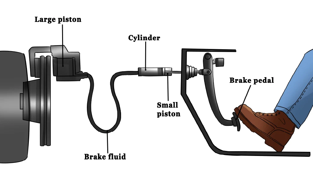
The primary function of the brake system is to slow or stop the vehicle speed. This is controlled by the brake pedals. When a person presses down the brake pads, the rotor that is attached to the wheel is controlled by the force. This is caused due to friction.

Types of brakes

There are various types of brakes classified according to the method of power, application, and operation.

By the method of power: Mechanical Brakes, Hydraulic Brakes, Air Brakes, Vacuum Brakes, Magnetic and Electrical brakes.

By the method of application: Service and Parking brakes are classified under the application.

By the method of operation: Manual, servo, and power operation are classified under the method of operation.

Types of Mechanical Brakes

Drum Brakes and Disc Brakes are the main two types of mechanical brakes.

A disc brake is a mechanism for stopping or slowing the wheel while in motion. It is usually made up of cast iron. But it can also be made of ceramic -matrix composites reinforced carbon-carbon.

A drum brake is made up of a brake drum attached or jointed inside a drum. It is a mechanism where a person presses the pad, and the vehicle stops due to the friction from the rotating drum.

Other few types of mechanical brakes are brand brakes and cone brakes.

Brand brake is a brake mainly used for bicycles. It is a tightened high friction pulley attached to the rotating axle.

Cone brake is one of the types of the drum brake, where the cone and the drum are in mating sections.

The friction brake saves the heat in disc while the brake is pressed and carries out the air slowly. In some emergencies, the brake prevents the slowing down of the vehicle. When traveling down a hill, the brake spins the drum and releases a large amount of heat without the increase in temperature.

Mechanical Braking System fluid

The design and the model of the mechanical braking system is a daring task for all engineers. The power of the braking system depends on the actuation force that is applied. Due to this force, the working surface experiences wear and friction. The breaking system decreases the forces and minimizes the friction. In this project, the study is on the best braking system by examining the defection and forces that are applied to the mechanical braking system for a simpler optimization process. It is very important to understand the action force and the friction that occurs and their performance to understand the nature of work to reduce the accident.

Brakes are usually used to move the axles and wheels. The vehicles engage the braking mechanism mainly for the racing cars. They are mainly used for wheel brakes, flights, helicopters, parachutes, and many other areas. In many brakes, friction is created from the kinetic energy to heat energy. The transformation of kinetic to potential energy is saved in the form of oil or air.

Conclusion

We have observed various methods of the mechanical braking system and its function in this project that helps in the daily works of engineers and other workers. In the analysis of brakes, it is observed that in the process of the braking system, one of the brake shoe displacement and force is bigger than the other side of the brake shoe. The mechanical braking system has been tested with 220lbs which is of good form. It is analyzed that the brake shoe force was in variation. The friction and displacement of the brake system are completely symmetric.

Other Projects to Try:

  1. Automatic Gear Control Mechanical Project
  2. Scramjet Engine Seminar Report | Mechanical Project
  3. Google Driverless Car Project | Mechanical Project
  4. TestPage
  5. Streetlight Monitoring System IOT Project

Filed Under: Mechanical Projects Tagged With: Mechanical Projects

Airless or Non-Pneumatic Tyres PPT

April 29, 2018 by ProjectsGeek Leave a Comment

Airless or Non-Pneumatic Tyres

Objective

Since several years vehicles have been rolling on the pneumatic tyres or air tyres. These types of tyres have major implications and were not good from safety point of view. In pneumatic tyres, there was a high possibility of the blowout which can cause the number of accidents using non-pneumatic tyres so it has a large impact on safety. If these vehicles are used then one need not worry about safety. Another benefit is that they can be reused and earlier tyres go flat and have to be thrown away so there was the need for the development of non-pneumatic tyres.

Airless or Non-Pneumatic Tyres

Existing system

A car is one of the major things that each person should have so there was the need for improved tyres which are safe and environmentally friendly. In pneumatic tyres the design is such that there is an inner core that holds pressurized air which is covered by the layer of rubber that is called as the tread. This tread keeps traction with the road and prevents slipping. But if this tyre wears down over time so it needs to be replaced. The main reason behind using this tyre was deformation. As the car moves the tyres rolls and the weight of the car pushing down the tyre causes it to flatten slightly. These tyres have both advantage and disadvantages. There is a possibility of blowout which makes it non-safe.

History

Initially, there was a craftsman known as Wheelwright who forged bands of iron and steel and tied the wheel together. Then this wheel was placed on wooden wheels of carts and dragons. John Dunlop tried to make his son’s bicycle comfortable to ride on which lead to the invention of pneumatic tyres.

Pneumatic tyres

If sometimes there is not enough required pressure in the tyre then the side tyre walls flex or bend causing the tyre to not to follow the desired line of steering. Due to these disadvantages, there was the need to create the airless tyre.

Working

There is a hub assembly which mounts to the axle and there are spokes arrayed in a pattern of wedges. There is a shear band forming the outer edge of the tyre. Then there is a tread that comes in contact with the surface of a road. When this tyre is running on the road spokes absorb road. These non-pneumatic tres have the positive impact.  SciTech’s airless tyre is said to be able to outlast the car. Airless tyres use the composite material. Tyres are the main part of automobiles and research on airless tres is still going on. The new technology will improve the safety of cars as well as have a positive impact. This will help to reduce accidents. There will also be the possibility of cost-effective tyres which will help the consumer.these are all due to advances in technology. For years vehicles have been running on pneumatic tyres but now there will be an improvement. The inventors have come with a new concept where tyres do not require air so there is a good future of these tyres.

Airless Tyres spoke tensions and lateral stiffness

 Advantages 

  • It eliminates the blowout and leakage.
  • It is flexible which provides the increase in surface area of contact
  • There is no maintenance needed.
  • It is durable and has the long life
  • It is environmental friendly.

This Tweel Airless tyres was developed in 2005 by Michelin. It is a combination of words tyre and wheel. In this, the tread and shear bands of the Tweel wheels will deform as the spokes band and then quickly go back to the initial shape. 

Applications

    • It is used in small vehicles like lawn movers and golf carts.
  • It is also used in military vehicles.

Download non pneumatic tyres ppt

Non-Pneumatic Tyres Abstract

Non-Pneumatic Tyres PPT Download

Non-Pneumatic Tyres Report

Other Projects to Try:

  1. Automatic Gear Control Mechanical Project
  2. Google Driverless Car Project | Mechanical Project
  3. Scramjet Engine Seminar Report | Mechanical Project
  4. 5 pen PC Technology | PPT and Project Report
  5. Car Sales System project in Java

Filed Under: Mechanical Projects Tagged With: Mechanical Projects

Scramjet Engine Seminar Report | Mechanical Project

April 25, 2018 by ProjectsGeek Leave a Comment

Scramjet Engine Seminar Report

Objective

The desire of man for speed and to fulfill his demands is growing so this lead to the objective of creating the jet engine which could fly high fast and a man immediately reaches its destination. This lead to the development of high-speed engine which has hyper sonic speed called as a scram jet engine. It is made in such a way that it achieves a very high speed. It is an engine with combustion taking in supersonic flow manner.

Scramjet Engine

History

During the second world war there was invented a jet fighter engine known as Heinkel which became the first aircraft and after that, there was an engine developed called WHITTLE. The jet engine works on Newton’s third law of motion, There are three main parts first compressor in which there are fans whose blades pull in air and send it through a channel then there is the combustion chamber and the third section is the turbine. This also has series of fans like the compressor.

Existing system

Earlier there were rockets which combine liquid fuel with liquid oxygen to generate thrust. But this aircraft can be smaller in size. During World War II there was the need of aircraft that could fly at hyper sonic speeds so this lead to the development of ramjets and scram jets. A ramjet is a form of the jet engine which uses the forward motion to compress the air.  Ramjet is a simple propulsion system for high-speed flight. It provides high thrust and low weight.

About the engine

The scram jet engine occupies the lower part of the vehicle. There are five engine and two vehicle components. The induction system compresses the air for processing by the other engine components. These achieve an adequate system without any moving parts like a compressor. The main component in an engine is an isolator. Then there is a combustion which provides efficient fuel-air mixing. It has a simplicity of design and less payload. There are few moving parts needed in this engine which simplifies both its design and maintenance. The turbojet engine which requires inlet fans and rotating compressor.

Scramjet Engine Seminar Report

Ramjet engine requires a high vehicle speed and it deaccelerates the incoming air whereas air flow in the scramjet is supersonic throughout the engine. It relies on combustion of fuel and oxidizer to produce thrust similar to conventional jet engines.

Scram jet means Supersonic Combustion Ramjet. It is its simplicity that acquires high velocity. These carry the fuel with it and get the oxidizer by combustion of oxygen. When mounted on a high-speed large amount of air go into the engine inlet and due to which the aircraft moves forward. Then the hot exhaust air goes through a nozzle which is used for accelerating the flow of the engine. The scram jet has very low thrust to weight ratios so acceleration is limitless. Modern rocket uses their own fuel but in scram jets, the coolant is the fuel itself and the oxidizer is also used. There is a much reduction of craft mass as fuel only need a tank, pumps so the scram jet involves only half an engine. There is a less amount of fuel and oxidizer used in scram jets which means a large percentage of cost reduction, Scram jets can be reused many times whether subject to extreme weather conditions.

Applications

  • It can be used in civil applications if one wants to travel from one place to another place one can do so within few minutes.
  • It is used in military applications as well. It can be used as a propel missile

Project Material Download

Scramjet Engine Abstract

Scramjet Engine Seminar Report

Scramjet Engine Seminar PPT

Other Projects to Try:

  1. Context Based Search Engine Final Year Project
  2. Search Engine using Python Project
  3. Mechanical Braking System Project
  4. Automatic Gear Control Mechanical Project
  5. Google Driverless Car Project | Mechanical Project

Filed Under: Mechanical Projects Tagged With: Mechanical Projects

Automatic Gear Control Mechanical Project

April 23, 2018 by ProjectsGeek Leave a Comment

Automatic gear control

Objective

There is an automatic gear control device for automobile system which helps in changing gear control without any problem. Whenever the load is applied then the rotational speed of the output rotation shaft is reduced to a required level. For solenoid valve, there is a push button which is used to activate or deactivate this valve. There is a gearbox arrangement which is used to change the gear speed from one speed to another. The main aim of this automatic gear changer control is that the automatic transmission connected to an automatic rotation shaft of this engine and the rotational output if the engine to the wheels and thus the gear changes.

This apparatus comprises of load device which is connected to output rotation shaft of the engine generating gear control signal I according to the increasing load of the load device when there is a gear changing control signal generated.

Automatic Gear Control

Advantages

  • It is the automatic method
  • It is helpful for drivers of the cars
  • There is a quick response achieved
  • This process is applicable to all types of two-wheeled vehicles

Existing system

Earlier there was no such automated stem and the gear used to be changed manually but now through this device, it can be changed automatically.

Pneumatic is the use of compressed gas to affect physical motion. There are centrally located compressors that powers cylinders and pneumatic devices are used to power in a cheaper and flexible way to a large number of devices. These systems are also used as a lubricant to avoid corrosion. As the compressed atmospheric air removes a small quantity of oil added to the compressor this gas is not much dangerous so one need not worry about poisonous leakage of gas which is just air. There is a lot of difference between pneumatic and hydraulics as pneumatic use compressed gas while hydraulics use liquid media such as oil.

Types of transmission

Manual transmission

A manual transmission is used in motorcycles and cars where gears are selected in order and manually. There is no automatic system and the clutch has to be used first before the gear is selected.

Automatic transmission

This system automatically changes the gear vehicle as the vehicle moves which frees the driver from having to shift the gears manually to achieve efficient driving.

Some reliable Pneumatic system has long operating lives which requires less maintenance.

It’s compressed gas can be stored.

Safety

There is a low chance of fire

Machines can be designed to be overload safe.

Some large devices are used as commercial equipment and some machines use a torque converter which provides variable gearing. The automatic transmission like continuous variable transmission frees the drivers from shifting the gears manually.

Automatic transmissions have various modes like:

Park

This is used to lock the output shaft of the transmission because of which vehicle can’t move in any direction. It is recommended to use the handbrake. Park is one of the two modes in which engine can be started or being neutral. Most automobiles use these selectors levels and there is a normal open inhibitor switch.

Solenoid value Automatic Gear Control

Reverse(R) 

It is used for reversing the vehicle backward.

Reverse position is electronically engaged by a switch on the brake pedal.

Neutral(N)

It is no gear which neutralizes all the gear transmission so that the vehicle can be moved freely. In this, the vehicle’s engine can be started.

Drive(D)

Its transmission allows the vehicle to move forward and accelerates through its range of gears.

Download Project Material

Project Abstract

Automatic Gear Control Project Report

Automatic Gear Control PPT

Other Projects to Try:

  1. Scramjet Engine Seminar Report | Mechanical Project
  2. Mechanical Braking System Project
  3. Google Driverless Car Project | Mechanical Project
  4. 5 pen PC Technology | PPT and Project Report
  5. TestPage

Filed Under: Mechanical Projects Tagged With: Mechanical Projects

Primary Sidebar

Tags

.Net Projects Download Android Project Ideas Android Projects Angular 2 Assembly Codes C # Projects C & C++ Projects C++ Projects Class Diagrams Computer Graphics Database Project Data Mining Projects DataScience Projects Datastructure Assignments Download Visual Basic Projects Electronics project Hadoop Projects Installation Guides Internet of Things Project IOS Projects Java Java Interview Questions Java Projects JavaScript JavaScript Projects java tutorial JSON JSP Projects Mechanical Projects Mongodb Networking Projects Node JS Projects OS Problems php Projects Placement Papers Project Ideas Python Projects seminar and presentation Struts

Search this Website


Footer

Download Java Project
Download Visual Basic Projects
Download .Net Projects
Download VB Projects
Download C++ Projects
Download NodeJs Projects
Download School Projects
Ask Questions - Forum
Latest Projects Ideas
Assembly Codes
Datastructure Assignments
Computer Graphics Lab
Operating system Lab
australia-and-India-flag
  • Home
  • About me
  • Contact Form
  • Submit Your Work
  • Site Map
  • Privacy Policy